Under Sink Plumbing Layout AAV Diagram: Guide
Under-Sink Plumbing Layout Guide: P-Trap, Drain Arm, and AAV Configuration Diagrams
Get under sink plumbing layout aav diagram guidance for P-trap height, drain arm slope, and correct AAV placement from the Home of the Patented Dual-Seal AAV.
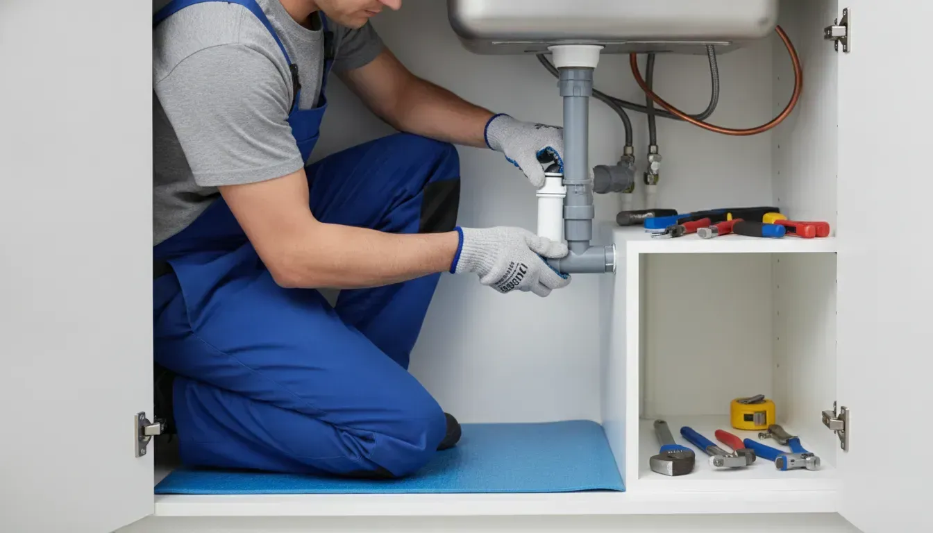
Under a sink, a dependable drain layout is more than a collection of fittings. The P-trap holds the water seal, the drain arm carries wastewater toward the branch drain, and the vent connection helps protect drainage flow from pressure problems. Getting those relationships right makes an installation easier to inspect, troubleshoot, and maintain.
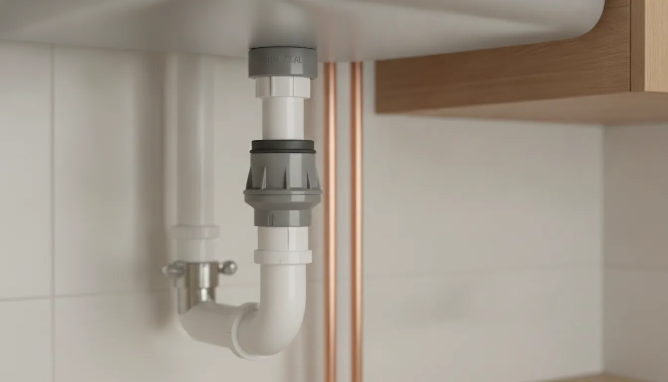
An under sink plumbing layout aav diagram should show the AAV connected to the fixture branch above the horizontal drain line. The P-trap and drain arm are arranged according to the manufacturer's instructions and applicable plumbing code. The AAV admits air when negative pressure develops, then reseals to help prevent sewer gases from escaping.
The diagram becomes much easier to follow when each component has a defined job. Start by identifying the trap, drain arm, sanitary tee, and vertical AAV connection, then consider how their position affects venting and access.
See instructions to get AAV layout guidance for your under-sink plumbing setup
How Under-Sink Plumbing Is Laid Out: The Key Components
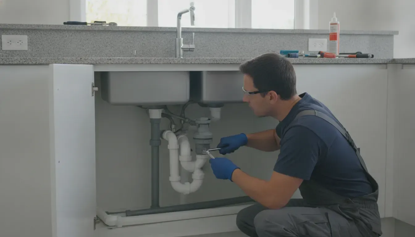
A typical under-sink plumbing layout connects the fixture drain to the building's drainage and venting system while keeping the water supply accessible for service. Each component has a defined role, and understanding how they relate makes an AAV installation easier to inspect and troubleshoot.
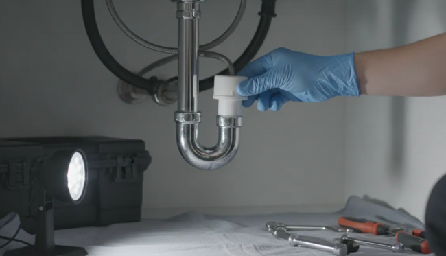
- P-trap: The curved section directly below the sink holds a water seal that helps block sewer gases from entering the room. The trap connects to the sink tailpiece on one side and the drain arm on the other. Keep the trap accessible rather than burying it behind a wall or cabinet finish.
- Drain arm: This is the horizontal pipe between the trap outlet and the sanitary tee or other connection to the drain stack. It carries wastewater away from the fixture and provides the branch connection where the venting arrangement is established. The arm should be laid out cleanly, without unnecessary bends or improvised extensions.
- Sanitary tee: On a typical fixture branch, the sanitary tee connects the drain arm to the larger drainage path while its upper opening provides the vertical vent connection. The tee's orientation matters. It should direct wastewater into the drain while allowing air to enter the branch when the fixture discharges.
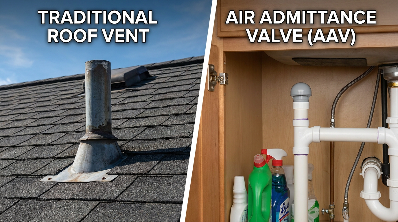
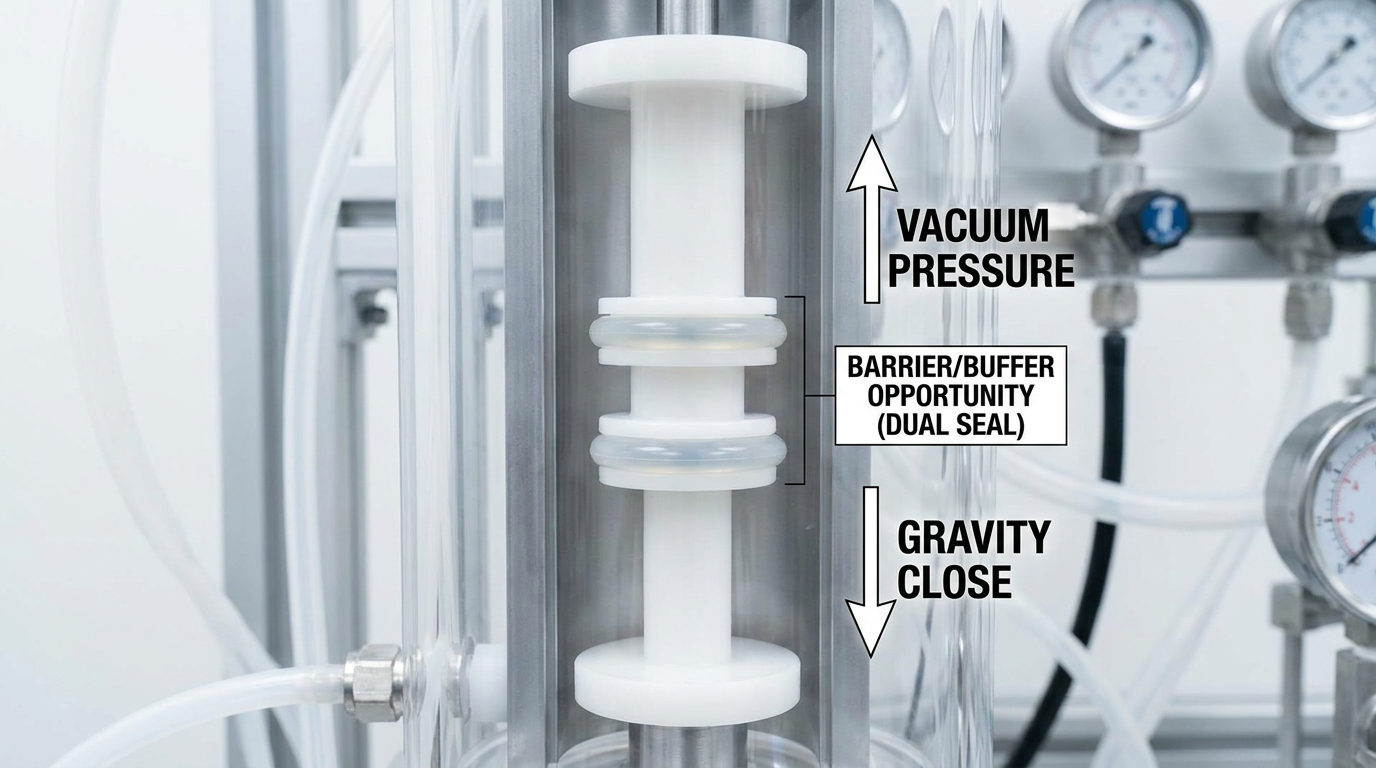
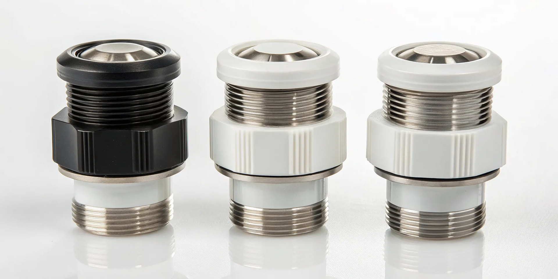
- Air admittance valve: Where a traditional vent connection is not practical, an AAV fits on the fixture branch at the designated vertical vent point. Commonly above the sanitary tee and above the horizontal drain line. The valve opens when negative pressure develops, admits air to protect the trap seal, then reseals. A dual-seal design adds a redundant barrier against sewer gas and odors when the valve is closed.
- Fixture supply stop valves: These shutoff valves sit on the hot and cold water supply lines below the sink. They are separate from the drain and vent system, but their position matters during installation because they need to remain reachable for maintenance or fixture replacement.
- Supply lines and tailpiece: Flexible or rigid supply lines connect the stop valves to the faucet. The tailpiece carries wastewater from the sink strainer down to the P-trap. Neither should be forced against the drain arm or valve assembly, since crowded cabinet interiors make inspections and future repairs more difficult.
For layouts that differ from a standard under-sink branch, review Tuuber's guidance on special plumbing configurations. The exact arrangement should follow the applicable code and the valve manufacturer's installation instructions.
Where Does the Air Admittance Valve Connect Under the Sink?
In a typical under-sink plumbing layout, the air admittance valve connects vertically to the fixture branch above the horizontal drain line. The usual connection point is a sanitary tee installed downstream of the P-trap, where the valve can admit air into the drain when negative pressure develops.
The arrangement matters because the AAV vents the fixture branch, not the water supply lines and not the trap itself. Wastewater leaves the sink through the trap and drain arm, then enters the branch drain. The AAV sits on the branch at the tee, with its opening positioned upward inside the cabinet. This gives the valve access to room air while keeping it above the portion of the drain that carries wastewater.
Why the valve must be above the horizontal drain
An AAV must be positioned above the horizontal drain line of the fixture it serves. Installing it too low can expose the valve to wastewater or backflow and can interfere with its operation. The valve should also be above the trap weir, the point where water begins to flow over the trap's internal bend. That vertical relationship allows the valve to respond to pressure changes in the fixture branch without becoming part of the drainage path.
When a fixture drains, the moving water can create negative pressure in the branch. The AAV opens to let air enter the system and reduce that pressure, then reseals automatically when the pressure normalizes. The closed seal helps prevent sewer gases and odors from entering the room. Tuuber's patented dual-seal design adds a second sealing point intended to support reliability while the valve performs this open-and-reseal function. See our full AAV installation guides for product-specific placement and connection details.
What to check before connecting an AAV
- Confirm that the sanitary tee is on the fixture branch downstream of the P-trap.
- Keep the valve connection vertical and above the horizontal drain line.
- Verify that the valve remains above the trap weir and accessible for inspection or replacement.
- Follow the manufacturer's instructions and the plumbing requirements adopted in your jurisdiction.
Question: Where does an air admittance valve connect under a sink?
Answer: An air admittance valve connects vertically to a sanitary tee on the fixture branch, downstream of the P-trap and above the horizontal drain line and trap weir. This position lets the valve admit air during negative pressure and reseal to help contain sewer gases.
P-Trap Height and Drain Arm Slope: Getting the Dimensions Right
Dimensioning matters in an under-sink vent layout. It must let wastewater drain freely while giving the air admittance valve a clear path to respond to pressure changes. Keep the drain arm sloped at a minimum of 1/4 inch per foot toward the drain. And place the AAV above the horizontal drain line and above the P-trap weir. The valve also needs to remain accessible for inspection and replacement.
The exact connection height depends on the fixture, cabinet, pipe sizes, and the manufacturer's instructions. Use the table below as a layout check, not as a substitute for the applicable plumbing code or the product instructions.
| Layout point | Correctly sized layout | Common dimension error |
|---|---|---|
| Drain arm slope | Maintain at least 1/4 inch of fall for every 1 foot of horizontal run toward the drain connection. | Installing the arm level, or creating a steep drop, can interfere with drainage and reduce the intended venting geometry. |
| P-trap weir | Keep the trap weir at a practical height below the AAV connection, with the trap outlet flowing into the sloped drain arm. | Mounting the AAV at or below the trap weir can expose the valve connection to drainage flow or leave insufficient vertical separation. |
| AAV position | Install the AAV vertically above the fixture's horizontal drain line and where air can enter the branch without obstruction. | Placing it below the horizontal line, on its side, or in a location blocked by the cabinet or stored items undermines access and operation. |
| Code and product instructions | Confirm location, accessibility, and installation details against the manufacturer's instructions and IPC Section 918. | Assuming one universal measurement applies to every sink, pipe arrangement, or jurisdiction can produce a layout that does not meet local requirements. |
These checks align with IPC Section 918, which requires AAVs to be installed according to the section and the manufacturer's instructions: read IPC Chapter 9, Section 918. For the valve itself, ASSE 1051 identifies performance requirements for individual and branch-type AAVs used in plumbing drainage systems: see the ASSE 1051 reference.
Before closing the cabinet, check that the trap, drain arm, and AAV are all supported. That the slope is visible rather than forced through a fitting, and that the valve remains reachable. Tuuber's dual-seal design is intended to help prevent sewer gas, odors, and siphoning, but correct placement is still essential to a reliable installation.
Sample Under-Sink Plumbing Layout and AAV Diagram: Single-Bowl Sink
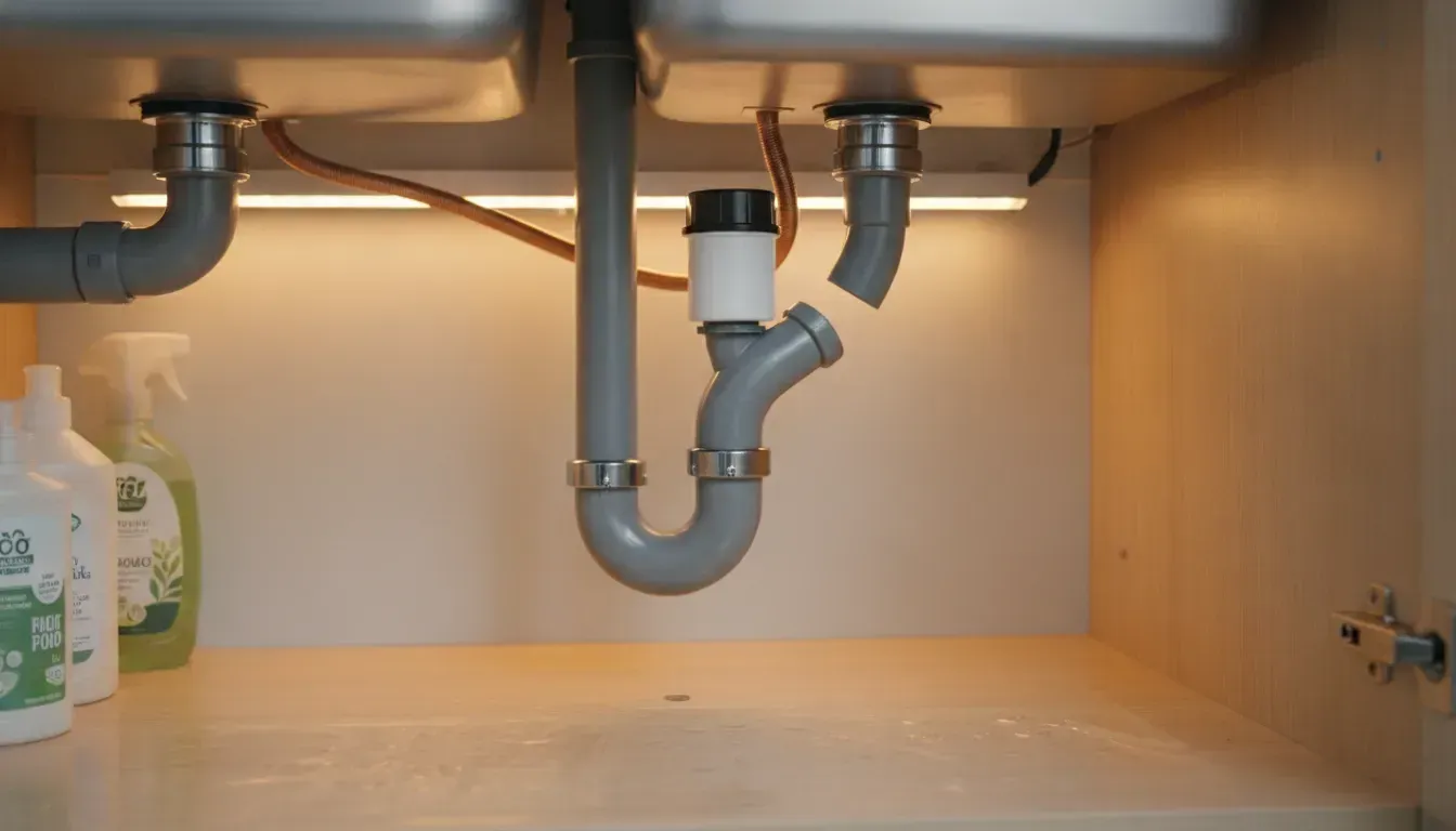
Use this single-bowl arrangement as a visual reference for tracing the fixture branch from the sink to the air admittance valve (AAV). The drain carries wastewater through the trap, while the AAV admits air when negative pressure develops in the branch. This layout keeps the valve accessible inside the cabinet and avoids running a traditional vent pipe through the structure and roof.
- Sink drain opening: Wastewater leaves the basket strainer through the sink tailpiece. Keep this connection aligned with the trap inlet so the trap does not need an unusual offset.
- P-trap: The trap holds a water seal that helps block sewer gases from entering the room. Its outlet connects to the fixture drain arm.
- Short drain arm: The drain arm runs from the trap toward the wall-side sanitary tee. It should maintain the required drainage slope and avoid unnecessary bends that can restrict flow.
- Sanitary tee: The tee connects the fixture branch to the vent opening above and the drain path below. In this example, the AAV connects to the upper opening of the tee.
- Vertically mounted AAV: Install the valve upright on the fixture branch, above the horizontal drain line and above the trap weir. The valve must remain accessible for inspection or replacement, rather than being buried behind a finished wall.
In a simplified diagram, read the flow from left to right or front to back as: single-bowl sink drain opening -> tailpiece -> P-trap -> drain arm -> sanitary tee -> branch drain. At the tee, the AAV rises vertically above the drain line. That position gives the valve access to air while keeping it out of the wastewater path. The valve should not be installed sideways or below the horizontal line it serves.
The vertical relationship matters at two points. First, the AAV must sit above the horizontal drain line so wastewater cannot enter the valve during normal drainage. Second, it must be above the trap weir, the point where water would spill over from the trap toward the drain arm. Exact placement and accessibility requirements depend on the applicable code and product instructions. The IPC Chapter 9 venting provisions provide the regulatory baseline, and the valve must be installed according to the manufacturer's instructions.
Tuuber's patented dual-seal design is intended to add reliability at the valve, helping prevent sewer gas, odors, and siphoning when the AAV is installed correctly. For the product-specific connection details and approved configurations, review our AAV installation guides before completing the rough-in.
Double-Bowl Sink with a Shared AAV: Configuration and Diagram
A double-bowl sink can use one properly sized AAV when both compartments connect to the same fixture branch. The two bowl drains join below the sink through a wye or tee. While the shared AAV is installed on the common branch above the higher of the two trap weirs. This arrangement allows one valve to admit air for both drains without placing a separate vent at each bowl.
How the shared configuration is arranged
- Each bowl has its own drain connection. The left and right basket strainers discharge through their respective tailpieces and trap connections.
- The drains join at a wye or tee. The fitting combines both outlets into one common fixture branch. A wye can provide a smoother directional transition, while a tee may be used where the approved layout and available space permit.
- The shared AAV connects to the common branch. Place the valve vertically on the branch after the two drains have joined, not beneath an individual bowl where it would vent only one side of the system.
- Keep the valve above the higher trap. The AAV must remain above the horizontal drain line it serves and accessible for inspection or replacement. Follow the valve manufacturer's instructions and the applicable plumbing code for the final location.
Reading the diagram flow
In a typical under sink plumbing layout aav diagram , follow the water path from left to right or right to left. Start at each bowl, trace both tailpieces into their individual traps, and then follow the two trap outlets to the shared wye or tee. From that junction, the common branch continues toward the wall drain. A short vertical riser from this common branch leads to the AAV, with the valve body upright and above the higher trap.
The airflow path works in the opposite direction during discharge. When draining water creates negative pressure in the branch, the AAV opens to admit air. Once pressure equalizes, it reseals automatically, helping prevent sewer gases from escaping through the valve. Tuuber's patented dual-seal design is intended to support reliable separation from sewer gases, odors, and siphoning. Review the guidance on preventing sewer gas leaks when evaluating valve reliability.
Because the shared valve serves both compartments, avoid burying it behind a fixed panel or installing it where the cabinet contents can obstruct the air inlet. The final configuration should remain accessible and should comply with the applicable venting requirements. IPC Chapter 9 is the regulatory baseline, but local requirements and the manufacturer's instructions still control the installation.
Common Under-Sink AAV Installation Mistakes to Avoid
A clean under-sink layout depends on more than connecting an AAV to the nearest drain opening. The valve needs the right position, airflow, access, and code context to operate as intended. Check these points before closing the cabinet or covering the piping.
- Installing the AAV below the horizontal drain line. An air admittance valve should be positioned above the horizontal drain line it serves. Mounting it too low can expose the valve to drainage conditions it was not designed to handle and can interfere with reliable venting. Plan the sanitary tee and vertical riser so the AAV remains upright and clearly above the drain arm.
- Allowing the cap or air inlet to become blocked. An AAV must be able to draw air into the drainage system when negative pressure develops. Do not bury the valve behind stored items, insulation, or cabinet materials, and do not seal off the cap. Keep the assembly accessible for inspection and replacement. A blocked inlet can prevent the valve from responding when the fixture drains.
- Forgetting that the AAV must sit above the trap weir. The trap protects the room from sewer gases, while the vent connection supports the fixture branch beyond the trap. Positioning the AAV below the trap weir creates an incorrect relationship between the trap and vent. Before fastening the piping, trace the path from the fixture through the P-trap and drain arm to confirm the valve is higher than the trap weir.
- Using an incorrect drain-arm slope. The drain arm needs a consistent slope that carries wastewater toward the branch drain without creating a low spot or an unnecessary rise. Excessive slope can cause water to outrun solids, while insufficient or uneven slope can leave standing water. Support the pipe, check it with a level, and follow the applicable plumbing requirements and the valve manufacturer's instructions.
- Skipping the local code check. A layout that looks practical may not be permitted in every jurisdiction. The International Plumbing Code requires AAVs to be installed according to the applicable code provisions and the manufacturer's instructions. Review local adoption, location, accessibility, and any restrictions before installation. Use this code-compliant plumbing layout guide as a starting point, then confirm the requirements enforced where the project is located.
Tuuber's patented dual-seal design adds a redundant sealing approach for reliability, but even a well-designed valve depends on correct installation. Keep the valve upright, unobstructed, accessible, and above the relevant drain and trap relationships. For product-specific placement details, compare the finished layout with the manufacturer's full AAV installation guides before testing the fixture.
Request your hired expert to review AAV installation of your under-sink AAV layout
Frequently Asked Questions
Can an AAV be installed under a sink?
Yes. An air admittance valve can be installed inside a sink cabinet when the location remains accessible and non-freezing. Position it above the horizontal drain line serving the fixture, and follow the valve listing, manufacturer instructions, and local plumbing requirements.
How high should an AAV be under a sink?
Install the valve as high as practical while keeping it accessible for inspection or replacement. Common layout guidance places it at least 4 inches above the horizontal branch drain and above the trap weir. But the product instructions and adopted local code control the final location.
What does an under-sink AAV diagram show?
A useful diagram shows the sink tailpiece flowing into the P-trap. The trap outlet connected to a sloped drain arm, and the sanitary tee with the AAV mounted vertically above it. The valve should remain on the fixture branch it serves, not below the drain line.
Does an AAV replace a traditional vent in every plumbing layout?
No. An AAV may provide an alternative where a conventional vent route is impractical, but its use depends on the fixture layout, accessibility, valve listing, and governing code. The IPC Chapter 9 AAV provisions require installation according to the code and the manufacturer's instructions. A dual-seal design can add reliability by helping prevent sewer gas and odors from escaping when the valve is closed.
Ready to Review Your Under-Sink Layout?
A clear P-trap, drain arm, and AAV arrangement helps you plan the installation before cutting pipe or closing the cabinet. For product and technical guidance to determine your configuration, refer to Tuuber Valves installation instructions. Share the sink layout, intended application, and any constraints with your hired professional so they can point you toward relevant AAV information and installation resources.